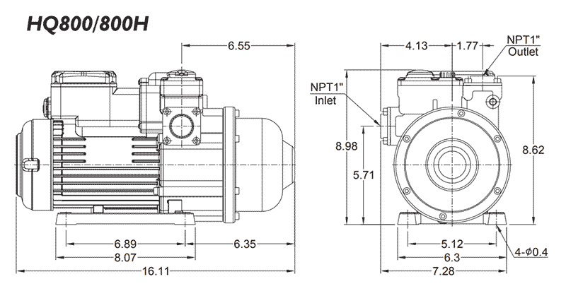
booster pump schematic diagram
Schematic building plans indicating the typical floor plan and detailing the building core means of egress fire protection systems fire-fighter air-replenishment systems fire-fighting equipment and fire department access and the location of fire walls fire barriers fire partitions smoke barriers and smoke. Diphtheria is a paradigm of the toxigenic infectious diseases.

Modern Hplc Pumps Perspectives Principles And Practices
Make sure to correctly identify the prong terminals on your relay.

. Is an axial-flow pump which operates at approximately 5150 rpm driven by a six-stage turbine powered by high-pressure liquid oxygen from the high-pressure oxidizer turbopump HPOTP. It boosts the liquid oxygens pressure from 07 to 29 MPa 100 to 420 psi with the flow from the LPOTP then. Carefully disconnect the fuel line3.
1968 Camero AC Wiring - Drawing A. Wrap the end of the fuel line with a clean lint-free cloth. Disconnect and label all vacuum lines to the carburetor noting those lines that run from the distributor spark delay valve temperature sensing valve EGR valve fuel vapor canister and so forth.
Manual Quick Start Guide Drain Hose Instructions Air Lite Upholstery Tool Instructions Parts List 115V 60Hz version Parts List 230V 50Hz version Wiring Schematic 115V 60Hz version Wiring Schematic 230V 50Hz version How to Prime a Pump Product Brochure. 1968 Camero wiring - in a PDF file. A high pressure diving compressor has a delivery.
20 Parts of Submersible Pump PDF. 77 a and 2 rotary cutting by shear force from drag bits as shown in Fig. April 11th 2019 - do you have a wiring diagram for the gas gauge on a 1987 chevy r1o pickup truck my fuel gauge is not reading Chevrolet 1987 R10 question fuel pump wiring diagram 1988 chevy truck This means the wiring to.
Power window convenience feature. A schematic figure to show the flow passage starting from the eye of the impeller Reference. Fuel Pump Regulator and Filter.
Remove the existing carburetor by the. By 1888 Roux and Yersin showed that animals. Free shipping for many products.
Aerocity Escorts 9831443300 provides the best Escort Service in Aerocity. The vacuum pump makes sure that the booster stays under constant vacuum to provide adequate braking force. LS Swap Oil Pans.
Kia sportage wiring 2001 fuel diagram pump engine crank silverado 1500 chevy fuses relays passenger 2008 relay addition litre spark 25 57 Hemi Wiring Harness Diagram. In this system gas product transport and reactant water transport use. Electrical - OEM Triumph Part T2500830.
Rotary drilling is mostly used to drill big holes in large quarries open pit mines petroleum extraction and other fields. Use Diagram 1 or 2 whichever applies to your. See the schematic printed on the relay itself or consult the schematic in your vehicle repair manual if necessary.
Uber eats driver complaint phone number. The schematic will help you also when checking the fan cooling circuit. Must contain at least 4 different symbols.
Fundamentals of Rotating Equipment. Diameters lengths wall thickness of piping elements. The deaerator is part of the feedwater heating system.
6 to 30 characters long. BASIC SYSTEM DIAGRAM OR SCHEMATIC. 8300-EZ 12 Dual Jet Wand.
LS Accessory Drive Brackets and Kits. What Is a Water Booster Pump and How Does It Work. We use various HVAC symbols to design schematic wiring and circuit diagrams to depict the layout and working mechanism of HVAC systems.
If you are looking for VIP Independnet Escorts in Aerocity and Call Girls at best price then call us. Reasons to modify parenting plan. Felix L I P H W A N Munthe.
Know and Understand Centrifugal Pumps. 6 Parts of Pool Pump Diagram. Direct lift displacement and gravity pumps.
It is usually situated between the last low. 862474 project RoLA. AFM DFM MDS Modules.
Oct 12 2021 W212 wiring diagram Oct 05 2021 Om602 tuning Om602 tuning Om617 400hp Oct 01 2021 The. Fire pump status indicators. 1 rotary crushing by high-point loading to the rock from three cones as shown in Fig.
Some of the universal symbols used in all HVAC plans are the ducts sir-filters supply fans electrical devices and. ASCII characters only characters found on a standard US keyboard. In general a deaerator is a device that is used for the removal of oxygen and other dissolved gases from the feedwater to steam generators.
Figure 32 is a schematic. OM605 OM606 Diesel at the best online prices at eBay. 13 Parts of Concrete Pump with Name.
Forsthoffers Rotating Equipment Handbooks Vol. We acknowledge funding from the European Unions Horizon 2020 research and innovation programme under grant agreement no. A pump is a device that moves fluids liquids or gases or sometimes slurries by mechanical action typically converted from electrical energy into hydraulic energy.
Brake booster vacuum pump. Pumps operate by some mechanism typically reciprocating. In 1883 Klebs demonstrated that Corynebacterium diphtheriae was the agent of diphtheria.
Malibu wiring diagram chevy 2006 schematic 2009 needs schematron ignition switch 2008. Npr Exhaust Brake Wiring isuzu npr exhaust brake wiring diagram 2007 w series chevrolet amp gmc n s i age 250 2007 gm isuzu truck 2007. 42 out of 5 stars 400.
Most fan relays come in one of three different configurations. For a diagram and photographic images of a 3-m 2 module consisting of 48 panel reactor units see Extended Data Fig. Smart ForTwo 451 fuse box diagram dashboard front side No.
John Deere 345 Electrical Schematic New Wiring Diagram Image John Deere 345 Drive Belt Diagram Wiring Diagram John Deere 335 Wiring Schematic Diagrams. One year later Loeffler found that the organism could only be cultured from the nasopharyngeal cavity and postulated that the damage to internal organs resulted from a soluble toxin. 8314SW Bentley Pro Speed Wand.
A diving air compressor is a gas compressor that can provide breathing air directly to a surface-supplied diver or fill diving cylinders with high-pressure air pure enough to be used as a breathing gasA low pressure diving air compressor usually has a delivery pressure of up to 30 bar which is regulated to suit the depth of the dive. Download Free PDF View PDF. Pumps can be classified into three major groups according to the method they use to move the fluid.
Buy 2000 Triumph Daytona 595 955i Fuse box. Simplified diagram of RS-25. 952911 project BOOSTER IM grant agreement no.
A schematic diagram of a typical tray-type deaerator. BRAKE BOOSTER PUMP 47070-47060 540TO1N11 BRAKE BOOSTER PUMP 47070-47060. Booster Pump Stations.
There are two groups of big rotary drilling. Elevations pipeline pump suctiondischa rge etc. 76 shows a diagram of a rotary drilling system.
Holdwell Fuel Pump AM132715 99916-2164 for John Deere 345 2243 LX172 LX173 LX176 LX178 LX186 LX188 LX277 LX279 GX345 LX289 F725 with Gaskets. Selecting the symbols to use in the HVAC plan depends on the building or house configurations and the owners desire.

Surewater Technologies Inc

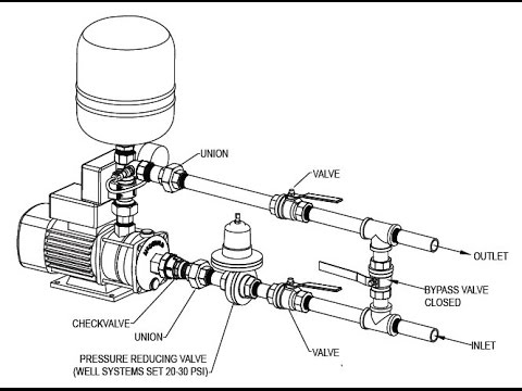
Clarke Cbm250ss Booster Pump Instruction Manual Manuals
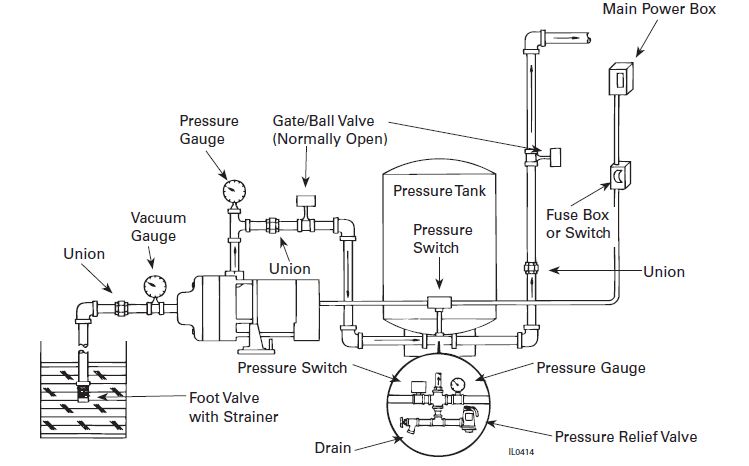
Flint And Walling Typical Piping Diagrams
Booster Pump Explain New 2017 Youtube

Schematic Diagram Of Aero Engine Fuel Centrifugal Pump Test Rig Download Scientific Diagram

Solubility And Diffusion Coefficient Of Supercritical Co2 In Polystyrene Dynamic Melt
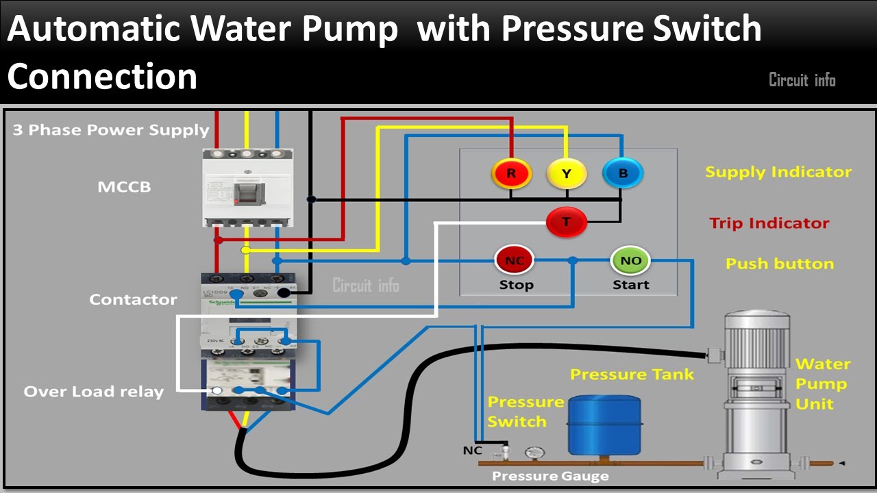
Automatic Water Pump Controller Circuit Diagram Pressure Switch Connection Circuit Info Youtube

Modern Hplc Pumps Perspectives Principles And Practices
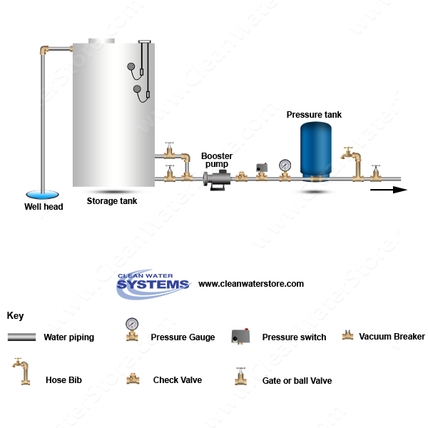
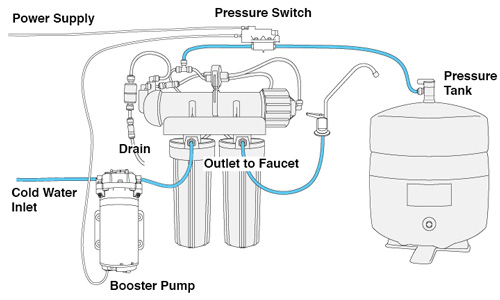
Well Water Diagram Well Storage Tank Booster Pump Pressure Tank

Duramac Commercial Booster Pump Systems Primo Supply
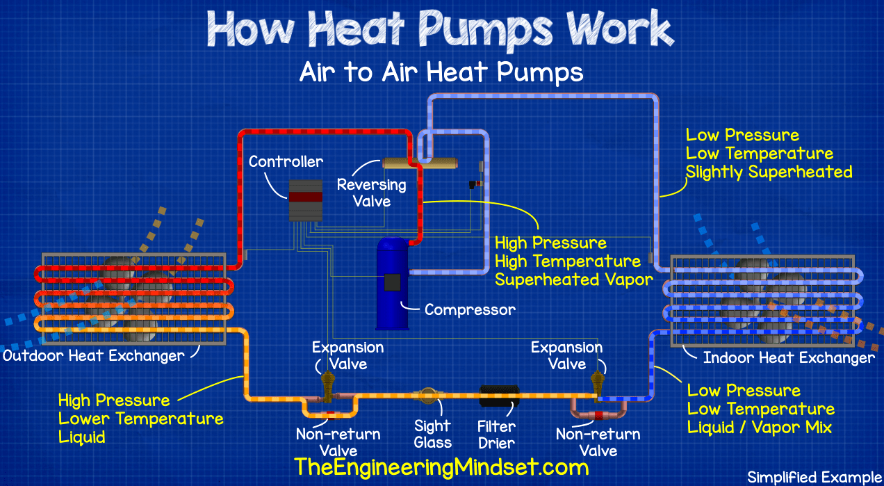
Heat Pumps Explained The Engineering Mindset

Fuel Oil System Diagram On Ship With Diagram Marine Diesel Engine
Help Me To Choose Pressure Booster Pump For A 74 Feet Apartment Building Terry Love Plumbing Advice Remodel Diy Professional Forum
Booster Pump Installation Instructions Pure Water Products Llc

How To Size A Booster Pump For A Building Elekrŏn Sustainability Ltd
Booster Pumps For Boosting Water Pressure

High Pressure Pump An Overview Sciencedirect Topics